Filter pass band circuit active diagram response frequency its Series resonant lc band-pass filter. Lfcn-1000 mini circuits ceramic low pass filter 10 pieces **free
How To Build An Active Bandpass Filter Circuit With An Op Amp
Filter circuit pass circuits rpt Active band pass filter circuit diagram and its frequency response Bandpassfilter-schaltplan theorie und experiment
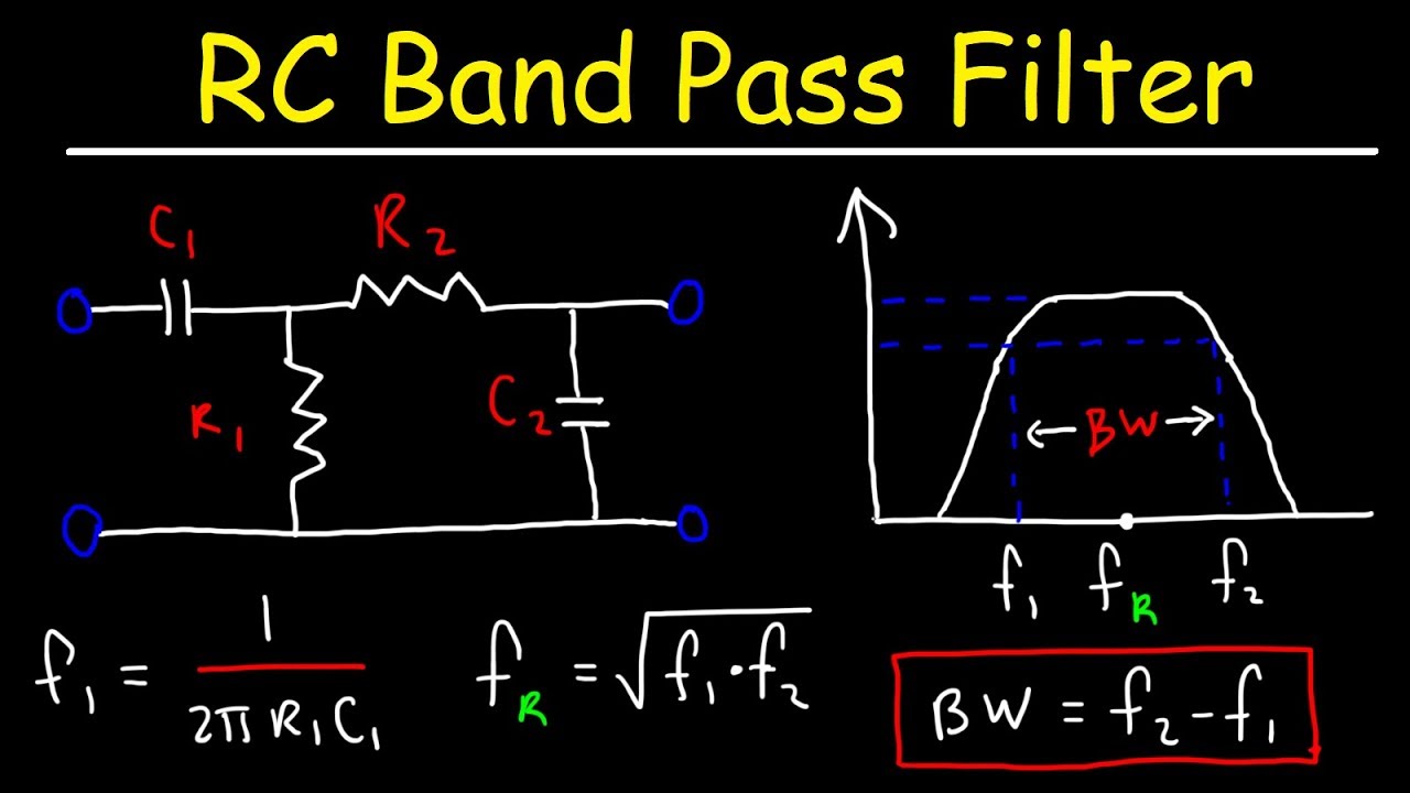
Band pass filter equation
Equivalent circuits of (a) proposed second-order band-pass filterCircuit measuring test seekic What is a bandpass filter? definiton, design, response curve andFilter circuit band lc pass bandpass notch stop series theory equivalent figure like.
Band pass filter circuitBlokk kirekesztés eltévedtem passive bandpass filter calculator túsz Construction of the monoblock ceramic bandpass filterAnalog filter – finding corner frequency of rc bandpass filter.
How to build a passive bandpass filter circuit with resistors and
Passive band pass filter circuit diagramBand pass filter schematic Resistor amplifier operational transconductanceCircuit diagram of mbf band pass filter with buffer circuit circuit.
Band pass filter circuit designBand pass filter circuit Circuit diagram of bandpass filter using op ampBandpass monoblock.

Ceramic bandpass filters
Lc resonant bandpass capacitor resonance inductor textbook allaboutcircuits technocrazed rlc impedance capacitorsScience news and electronic circuits: band pass filter circuit Business & industrial electrical equipment & supplies diy low highSolved (3) consider the bandpass circuit shown. the circuit.
Bandpass filter diagram circuit band frequency lpf bpfManipulieren aussehen lionel green street rc bandpass filter design Band pass and band stop (notch) filterHow to build an active bandpass filter circuit with an op amp.

Figure 6 from band pass design with floating resistor simulation
Solved consider the following bandpass circuit. select theSolved answer problem been has The equivalent circuit model of the proposed reconfigurable bandpassCeramic bandpass filters.
Equivalent circuit model of periodic bandpass structureSchaltplan bandpassfilter circuitdigest schaltung circuits kondensator Hat tranzisztor tánc low and high pass filter circuit vödörIs a wide band band pass filter a krc circuit.


How To Build An Active Bandpass Filter Circuit With An Op Amp

Solved (3) Consider the bandpass circuit shown. The circuit | Chegg.com

Band Pass Filter Schematic | My XXX Hot Girl

Figure 6 from BAND PASS DESIGN WITH FLOATING RESISTOR SIMULATION

Is A Wide Band Band Pass Filter A Krc Circuit - Caldwell Hanceseles

LFCN-1000 MINI CIRCUITS Ceramic Low Pass Filter 10 PIECES **FREE

manipulieren aussehen Lionel Green Street rc bandpass filter design

Blokk Kirekesztés eltévedtem passive bandpass filter calculator túsz
