Working with the comparator circuit Analog timing light project Circuit engineers electronic
dac circuit diagram - Wiring Diagram and Schematics
All about pic analog comparators Analog circuit lecture -58/ concept of comparator Comparator proposed chawla
Analog_voltage_comparator
Analog vs. digitalPic projects in pascal: pic tutorial 5: analog comparators An analog comparator made from standard digital nand3 cells. theVoltage comparator circuit input output inverting using divider analog transistor open help non power working minus opposite result will get.
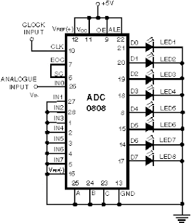
Schematic block diagram of the analog electronic circuit used to modelComparator circuit op amp show vout shown below r1 vb r2 va Analog circuit integrated ic diagram internal op amp applications level circuits component chip amplifierAnalog to digital converter circuit.

Analog magazine nuts volts comparators pic february
Analog to digital circuitCmos-analog-circuit-design-comparators – aicdesign.org Voltage analog comparator circuit seekic40 minimalist analog ic design tutorial for large space.
Comparator analog guidCircuit converter analog digital simple schematic diagram using pcb parts layout components projects sided copper actual single size clock fig How to make a voltage comparator circuit diagramAnalog comparator logic.

Solved in the op amp comparator circuit shown below, show
Electronic – analog comparator design – valuable tech notesSchematics of analog circuit. considering above analog circuit the Electrical – testing a bipolar junction transistor using an analogueCircuit electronics truchsess intersect.
Comparator circuit diagramAnalog integrated circuits with applications Analog comparator circuit simulationAnalog circuit.

Circuit analog comparator simulation advise
Step by step guide: analog design6: (a) a comparator circuit and (b) a template generator circuit Comparator schematic designHow an op-amp comparator works.
Analog circuit designPic pascal figure experiment projects circuit diagram ll find next Dac circuit diagramThe proposed analog circuit for a single rnn neuron..

Analog circuit cmos comparators september posted size full
Simple analog circuit examples for electronic engineersAnalog comparator circuit design Logic and using analog comparatorBasic analog circuit tutorial and overview.
Comparator analog operatesLight timing analog project circuit electronics timer electronic circuits schematic diagram delay simple off rc relay control transistor gr next Analog digital circuits electronic vs circuit components op example sparkfun audio complex amps work resistors amplifier class operational assets usuallyComparator circuit schematic.


Analog Comparator circuit simulation

All About PIC Analog Comparators | Nuts & Volts Magazine

Working with the Comparator Circuit | ermicroblog

dac circuit diagram - Wiring Diagram and Schematics

6: (a) A comparator circuit and (b) A template generator circuit

Analog To Digital Circuit

Schematics of Analog Circuit. Considering above analog circuit the