Car audio system anti theft security Anti theft alarm circuit diagram Anti theft alarm for bikes circuit connection diagram
Anti Theft Automobile Alarm Circuit
Circuit alarm car automotive theft anti gr next ne555 power easy circuits produce fewer paragraph components use Anti theft alarm for vehicles wiring diagram schematic ~ circuit wiring Anti theft automobile alarm circuit
Anti theft system for cars pdf
Car anti theft system circuit diagramPvc electric vehicle anti theft alarm system at rs 290/piece in Certified anti-theft car alarm system with cut-out in kenyaCircuit alarm diagram theft anti april.
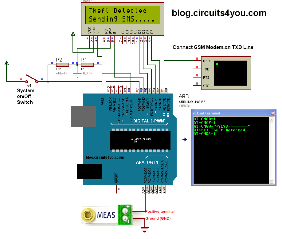
Loop-based anti-theft alarmCar alarm circuit : automotive circuits :: next.gr Theft anti based diagram circuit loop alarm electronics electronicsforu projects fig power using articleTheft system anti vehicle gsm sensor using circuit vibration modem step programming.

Circuit car system audio diagram theft anti security plug glow control module alarm cd4093 simple scheme 9v schematic electronic battery
Alarm theft anti circuit wireless diagram soldering post reflow wave previous(pdf) design of an anti-theft alarm system for vehicles using iot Alarm theft circuit anti touch type seekicAnti-theft car alarm circuit.
Theft anti alarm circuit diagramTouch-type anti-theft alarm circuit Alarm diagram car wiring system security manual vehicle chapman installation start auto systems theft do hill guide schematics american instructionsAnti theft diagram circuit car guard buzzer protection schematic electronic.
Anti theft alarm system using force sensor and arduino – circuit schools
Theft bicycle circuit diagram alarm anti bill materialAnti-theft alarming system : 5 steps The automobile and american life: auto theft alarm systems: a brief historyCircuit theft anti device bicycle guard electronicsforu diagram vmr available.
Vehicle anti-theft system using gsm modem and vibration sensorDesigned circuit diagram of anti-theft system Bicycle anti-theft alarm circuit diagramAnti theft alarm.
Anti theft 2 way alarm ( wiring diagram ) easiest way to install
Theft alarm circuit diagramCertified anti-theft car alarm system with cut-out in kenya Security circuits theft alarm anti electronics systems part improved immobilizer pulsed figure hasCar anti-theft protection with buzzer.
Homemade car alarm: the benefits and how to make the deviceAnti-theft control system circuit Anti-theft device for bicycleAnti theft system for cars pdf.

A wireless anti-theft alarm circuit diagram
Pocket sized anti theft alarm circuit using ic gadgetronicxSecurity electronics systems and circuits — part 10 Anti theft alarm circuit diagramElectronic circuit, circuit diagram, anti theft.
.


Pocket Sized Anti Theft Alarm Circuit Using Ic Gadgetronicx | My XXX

Anti Theft Automobile Alarm Circuit

Electronic Circuit, Circuit Diagram, Anti Theft

Anti Theft Alarm Circuit Diagram

Anti-theft Device for Bicycle | Detailed Circuit Diagram Available

Touch-type anti-theft alarm circuit - Control_Circuit - Circuit Diagram
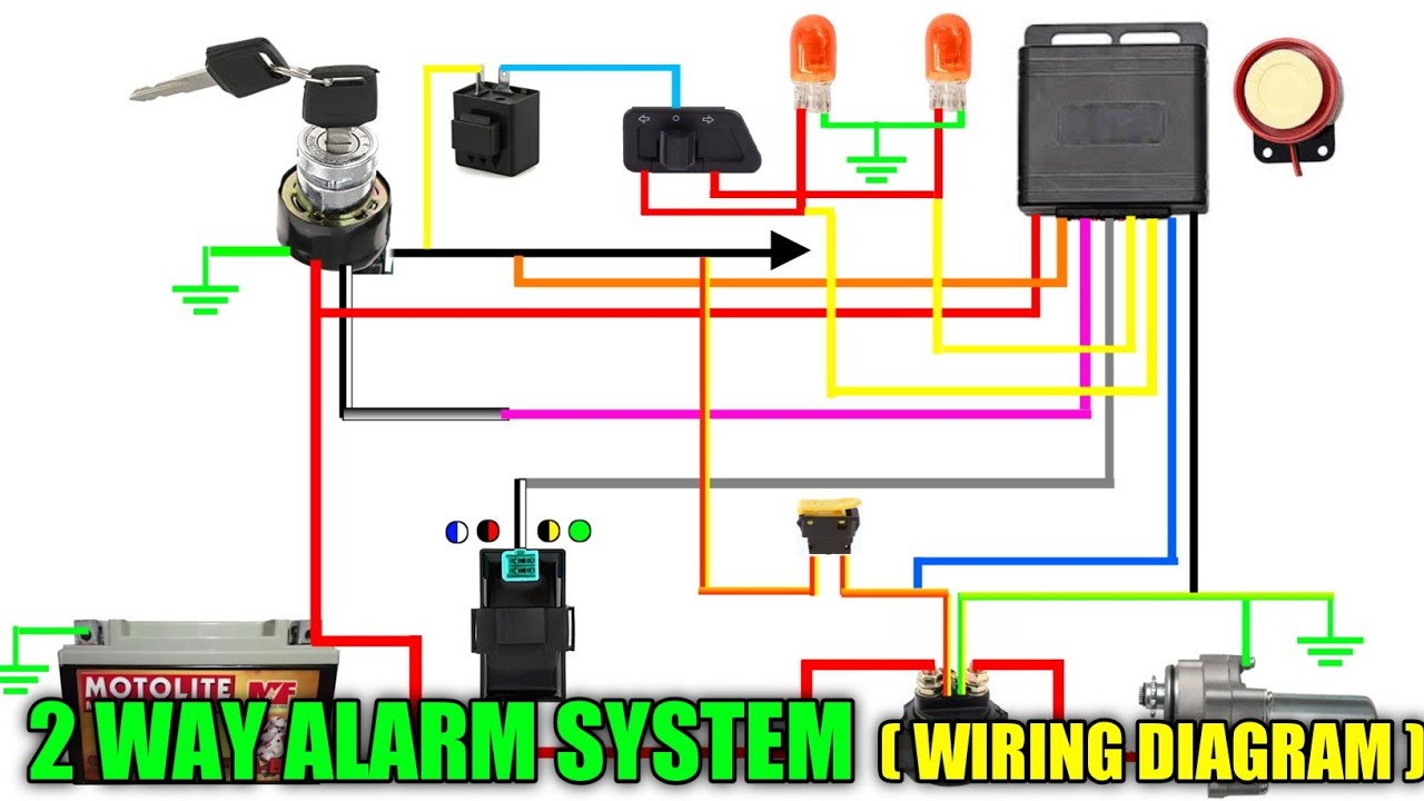
ANTI THEFT 2 WAY ALARM ( WIRING DIAGRAM ) EASIEST WAY TO INSTALL - YouTube
